


Recently, the alloy research team of Shanghai Institute of Applied Physics (SINAP), Chinese Academy of Sciences (CAS) has made progress in understanding the influence of phosphide impurity on corrosion behavior of UNS N10003 alloy in molten fluoride salt. The article entitled “Corrosion behavior of UNS N10003 alloy in molten LiF-BeF2-ZrF4 with phosphide impurity”, has been published in the Corrosion Science. Associate Prof. Hongxia Xu is the first author, and Prof. Bin Leng and Prof. Hefei Huang are the corresponding authors.
UNS N10003 alloy is the main structural material and LiF-BeF2-ZrF4 (FLiBeZr) is the fuel carrier salt for Thorium Molten salt Reactor (TMSR). During the fabrication of FLiBeZr salt, phosphide impurity is included from separating and purifying the BeF2 raw material if tributyl phosphate (TBP) is used as the extractant. However, in contrast to the extensive studies on the effects of impurities including moisture, metallic ions, and oxyanions on the corrosion of UNS N10003 alloy in molten fluoride salts, the attention paid to phosphide impurity is too scarce. To understand the influence of phosphide on the corrosion behavior of UNS N10003 alloy, the static immersion test of UNS N10003 alloy in FLiBeZr with 230 ppm phosphide at 700 °C for 100h and 400h were performed. The characterization of corrosion layers and products were examined by XRD, SEM and TEM techniques.
Results show that an outer layer of Ni3P and an inner layer of mixed Ni3P and Mo3Ni2P1.18 formed on the alloy surface after corrosion. The depth of both corrosion layers increased linearly with the increasing immersion time and suffered severe spallation after 400 h. Cr and Fe were depleted in the inner corrosion layer, indicating that the phosphide layers were not protective and may accelerate corrosion. Therefore, the existence of phosphide impurities in molten fluoride salts should be carefully removed through salt purification for future applications.
This work was financially supported by the National Natural Science Foundation of China (Grant No.12005289), and State Key Laboratory of Particle Detection and Electronics, University of Science and Technology of China (USTC) (Grant No. SKLPDE-KF-202316).
Link: https://doi.org/10.1016/j.corsci.2023.111635
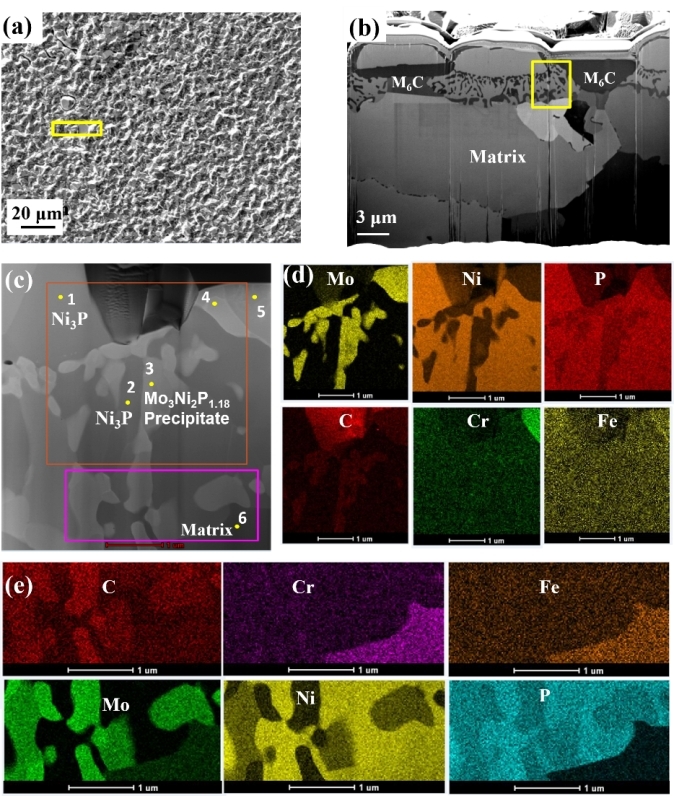
Fig.1 TEM analysis of corrosion products formed on the alloy sample surface after corrosion for 100 h: (a), (b) FIB milling position; (c) STEM mode image; (d), (e) corresponding EDS mappings of the areas within the orange rectangle and pink rectangle, respectively in (c)
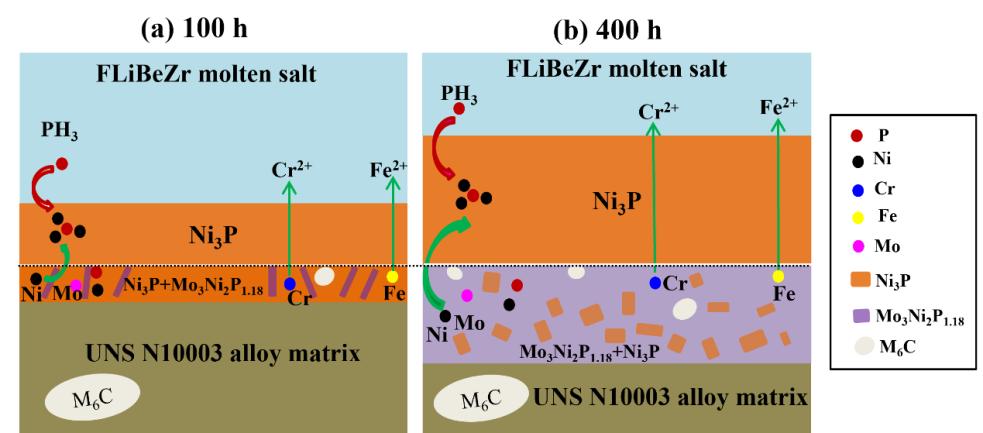
Fig. 2. Corrosion mechanism of UNS 10003 alloy in molten FLiBeZr with P impurity